 Use case diagram is a behavioral UML diagram type and frequently used to analyze various systems. They enable you to visualize the different types of roles in a system and how those roles interact with the system. This use case diagram tutorial will cover the following topics and help you create better use cases.
Importance of Use Case Diagrams
As mentioned before use case diagram are used to gather a usage requirement of a system. Depending on your requirement you can use that data in different ways. Below are few ways to use them.
- To identify functions and how roles interact with them – The primary purpose of use case diagrams.
- For a high level view of the system – Especially useful when presenting to managers or stakeholders. You can highlight the roles that interact with the system and the functionality provided by the system without going deep into inner workings of the system.
- To identify internal and external factors – This might sound simple but in large complex projects a system can be identified as an external role in another use case.
Use Case Diagram objects
Use case diagrams consist of 4 objects.
- Actor
- Use case
- System
- Package
The objects are further explained below.
Actor
Actor in a use case diagram is any entity that performs a role in one given system. This could be a person, organization or an external system and usually drawn like skeleton shown below.
Use Case
A use case represents a function or an action within the system. Its drawn as an oval and named with the function.
System
System is used to define the scope of the use case and drawn as a rectangle. This an optional element but useful when your visualizing large systems. For example you can create all the use cases and then use the system object to define the scope covered by your project. Or you can even use it to show the different areas covered in different releases.
Package
Package is another optional element that is extremely useful in complex diagrams. Similar to class diagrams, packages are used to group together use cases. They are drawn like the image shown below.
Use Case Diagram Guidelines
 Although use case diagrams can be used for various purposes there are some common guidelines you need to follow when drawing use cases.
These include naming standards, directions of arrows, placing of use cases, usage of system boxes and also proper usage of relationships.
Relationships in Use Case Diagrams
There are five types of relationships in a use case diagram. They are
- Association between an actor and a use case
- Generalization of an actor
- Extend relationship between two use cases
- Include relationship between two use cases
- Generalization of a use case
We have covered all these relationships in a separate blog post that has examples with images. We will not go into detail in this post but you can check out relationships in use case diagrams > .
How to Create a Use Case Diagram
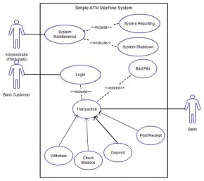
Up to now you’ve learned about objects, relationships and guidelines that are critical when drawing use case diagrams. I’ll explain the various processes using a banking systems as an example.
Identifying Actors
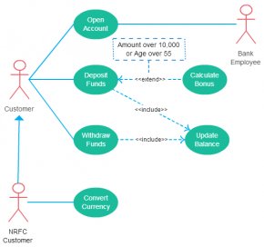
Actors are external entities that interact with your system. It can be a person, another system or an organization. In a banking system the most obvious actor is the customer. Other actors can be bank employee or cashier depending on the role your trying to show in the use case.
An example of an external organization can be the tax authority or the central bank. Loan processor is a good example of external system associated as an actor.
Identifying Use Cases
Now it’s time to identify the use cases. A good way to do this is to identify what the actors needs from the system. In a banking system a customer will need to open accounts, deposit and withdraw funds, request check books and similar functions. So all of these can be considered as use cases.
Top level use cases should always provide a complete functions required by an actor. You can extend or include use cases depending on the complexity of the system.
Once you identify the actors and the top level use case you have basic idea of the system. Now you can fine tune it and add extra layers of detail to it.
Look for Common Functionality to use Include
Look for common functionality that can be reused across the system. If you find two or more use cases that share common functionality you can extract the common functions and add it to a separate use case. Then you can connect it via the include relationship to show that its always called when the original use case is executed. ( see the diagram for an example ).
YOU MIGHT ALSO LIKE

Share this Post
latest post
-
 Dance Festivals Melbourne August 14, 2024
 -
 Jewish Film Festival Melbourne August 7, 2024
 -
 Christmas Festival Melbourne July 31, 2024
 -
 Australia Festival July 24, 2024
 -
 Sustainable Festival Melbourne July 17, 2024
 -
 Sustainable Living Festival Melbourne July 10, 2024
 -
 Writers Festivals Australia July 3, 2024
 -
 Chinese Festival Melbourne June 26, 2024
 -
 Melbourne Sustainability Festival June 19, 2024